マイクロビットとI2C電子ペーパモジュールでデジタル温度計を造ってみる
今回はマイクロビットでI2C電子ペーパモジュールを使ってみるの続きになります。
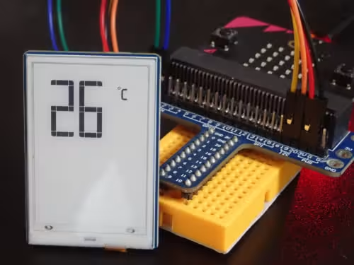
WaveShare 1.9インチ 91セグメント I2C電子ペーパモジュール(以後、e-paperと略す)をマイクロビットにつなぎ、マイクロビットに内蔵されている温度センサーから得られた結果をe-paperに出力します。
マイクロビットとe-paperとの接続は上記のURLを参考にします。
先に作成したコードを掲載します。
from microbit import *

RST_PIN  = pin0
BUSY_PIN = pin1

ADDS_COM        = 0x3C #60
ADDS_DATA       = 0x3D #61

DSPNUM_WB = [0xFF, 0xFF, 0xFF, 0xFF, 0xFF, 0xFF, 0xFF, 0xFF, 0xFF, 0xFF, 0xFF, 0xFF, 0xFF, 0xFF, 0xFF]  # black
DSPNUM_WW = [0x00, 0x00, 0x00, 0x00, 0x00, 0x00, 0x00, 0x00, 0x00, 0x00, 0x00, 0x00, 0x00, 0x00, 0x00]  # white

numbers = [
    [0xbf, 0x1f],  # 0
    [0x1f, 0x00],  # 1
    [0xfd, 0x17],  # 2
    [0xf5, 0x1f],  # 3
    [0x47, 0x1f],  # 4
    [0xf7, 0x1d],  # 5
    [0xff, 0x1d],  # 6
    [0x21, 0x1f],  # 7
    [0xff, 0x1f],  # 8
    [0xf7, 0x1f]   # 9
]

radix_point = 0x20
degree_centigrad = 0x05
Fahrenheit_degree = 0x06
BLE = 0x08
POW = 0x10
First_black = 0x1f
First_white = 0x00


class EPD:
    def reset(self):
        RST_PIN.write_digital(1)
        sleep(200)
        RST_PIN.write_digital(0)
        sleep(20)
        RST_PIN.write_digital(1)
        sleep(200)

    def send_command(self, i):
        i2c.write(ADDS_COM, bytes([i]))
        sleep(1)

    def send_data(self, i):
        i2c.write(ADDS_DATA, bytes([i]))
        sleep(1)

    def ReadBusy(self):
        while(BUSY_PIN.read_digital() == 0):      # 0: idle, 1: busy
            sleep(1)
        sleep(10)


    # DU waveform white extinction diagram + black out diagram
    # Bureau of brush waveform
    def lut_DU_WB(self):
        self.send_command(0x82)
        self.send_command(0x80)
        self.send_command(0x00)
        self.send_command(0xC0)
        self.send_command(0x80)
        self.send_command(0x80)
        self.send_command(0x62)

    # GC waveform
    # The brush waveform
    def lut_GC(self):
        self.send_command(0x82)
        self.send_command(0x20)
        self.send_command(0x00)
        self.send_command(0xA0)
        self.send_command(0x80)
        self.send_command(0x40)
        self.send_command(0x63)

    # 5 waveform  better ghosting
    # Boot waveform
    def lut_5S(self):
        self.send_command(0x82)
        self.send_command(0x28)
        self.send_command(0x20)
        self.send_command(0xA8)
        self.send_command(0xA0)
        self.send_command(0x50)
        self.send_command(0x65)

     # temperature measurement
    # You are advised to periodically measure the temperature and modify the driver parameters
    # If an external temperature sensor is available, use an external temperature sensor
    def Temperature(self):
        # micro:bit function temperature sensor.
        VAR_Temperature = temperature()

        if ( VAR_Temperature < 10 ):
            self.send_command(0x7E)
            self.send_command(0x81)
            self.send_command(0xB4)
        else:
            self.send_command(0x7b)
            self.send_command(0x81)
            self.send_command(0xB4)

        self.ReadBusy()
        self.send_command(0xe7)    # Set default frame time

        # Set default frame time
        if (VAR_Temperature<5):
            self.send_command(0x31) # 0x31  (49+1)*20ms=1000ms
        elif (VAR_Temperature<10):
            self.send_command(0x22) # 0x22  (34+1)*20ms=700ms
        elif (VAR_Temperature<15):
            self.send_command(0x18) # 0x18  (24+1)*20ms=500ms
        elif (VAR_Temperature<20):
            self.send_command(0x13) # 0x13  (19+1)*20ms=400ms
        else:
            self.send_command(0x0e) # 0x0e  (14+1)*20ms=300ms

    # Note that the size and frame rate of V0 need to be set during initialization,
    # otherwise the local brush will not be displayed
    def init(self):
        i2c.init()

        self.reset()

        self.send_command(0x2B) # POWER_ON
        sleep(10)
        self.send_command(0xA7) # boost
        self.send_command(0xE0) # TSON
        sleep(10)
        self.Temperature()

    def Write_Screen(self, image):
        self.send_command(0xAC) # Close the sleep
        self.send_command(0x2B) # turn on the power
        self.send_command(0x40) # Write RAM address
        self.send_command(0xA9) # Turn on the first SRAM
        self.send_command(0xA8) # Shut down the first SRAM

        for j in range(0, 15):
            self.send_data(image[j])

        self.send_data(0x00)
        self.send_command(0xAB) # Turn on the second SRAM
        self.send_command(0xAA) # Shut down the second SRAM
        self.send_command(0xAF) # display on
        self.ReadBusy()
        # IIC.delay_ms(2000)
        self.send_command(0xAE) # display off
        self.send_command(0x28) # HV OFF
        self.send_command(0xAD) # sleep in


    def Write_Screen1(self, image):
        self.send_command(0xAC) # Close the sleep
        self.send_command(0x2B) # turn on the power
        self.send_command(0x40) # Write RAM address
        self.send_command(0xA9) # Turn on the first SRAM
        self.send_command(0xA8) # Shut down the first SRAM

        for j in range(0, 15):
            self.send_data(image[j])

        self.send_data(0x03)

        self.send_command(0xAB) # Turn on the second SRAM
        self.send_command(0xAA) # Shut down the second SRAM
        self.send_command(0xAF) # display on
        self.ReadBusy()
        # IIC.delay_ms(2000)
        self.send_command(0xAE) # display off
        self.send_command(0x28) # HV OFF
        self.send_command(0xAD) # sleep in

    def sleep(self):
        self.send_command(0x28) # POWER_OFF
        self.ReadBusy()
        self.send_command(0xAC) # DEEP_SLEEP

        sleep(2000)
        RST_PIN.write_digital(0)

# Split a two-digit number.
def divide_number(i):
    l = []
    tens = ""
    if i >= 10:
        tens = str(i)[0]
        ones = str(i)[1]
    else:
        ones = str(i)[0]

    if len(tens) > 0:
        l = numbers[int(tens)]
    else:
        l = [0x00, 0x00]

    n = numbers[int(ones)]
    l.append(n[0])
    l.append(n[1])
    return l

print("epd1in9 Demo")

epd = EPD()
print("init and Clear")

epd.init()

epd.lut_5S()
epd.Write_Screen(DSPNUM_WW)

sleep(500)

epd.lut_GC()
epd.Write_Screen1(DSPNUM_WB)
sleep(500)
epd.Write_Screen(DSPNUM_WW)
sleep(500)

epd.lut_DU_WB()
sleep(500)

while True:
    # current temporature
    tmpList = divide_number(temperature())
    epd.Write_Screen([
        0x00,
        tmpList[0],
        tmpList[1],
        tmpList[2],
        tmpList[3],
        0x00,
        0x00,
        0x00,
        0x00,
        0x00,
        0x00,
        0x00,
        0x00,
        degree_centigrad,
        0x00
    ])
    sleep(1000*60)
※公式サイトのサンプルコードを参考にして改変しています。
https://github.com/inunosinsi/e-paper_on_microbit/blob/main/current_temporature.py
今回のコードは1分毎に温度を取得し、e-paperに出力します。
温度の出力に関して、
print("epd1in9 Demo")

epd = EPD()
print("init and Clear")

epd.init()

epd.lut_5S()
epd.Write_Screen(DSPNUM_WW)

sleep(500)

epd.lut_GC()
epd.Write_Screen1(DSPNUM_WB)
sleep(500)
epd.Write_Screen(DSPNUM_WW)
sleep(500)

epd.lut_DU_WB()
sleep(500)
の箇所の最初の手続きはそのまま残してあります。
while True:
    # current temporature
    tmpList = divide_number(temperature())
    epd.Write_Screen([
        0x00,
        tmpList[0],
        tmpList[1],
        tmpList[2],
        tmpList[3],
        0x00,
        0x00,
        0x00,
        0x00,
        0x00,
        0x00,
        0x00,
        0x00,
        degree_centigrad,
        0x00
    ])
    sleep(1000*60)
が温度の出力の箇所になります。
tmpList = divide_number(temperature())
の箇所でマイクロビットの温度センサーが温度のデータを取得し、e-paperで出力できるように、10の位の数字と1の位の数字を分け、出力用のリストに再生成します。
epd.Write_Screen([
    0x00,
    tmpList[0],
    tmpList[1],
    tmpList[2],
    tmpList[3],
    0x00,
    0x00,
    0x00,
    0x00,
    0x00,
    0x00,
    0x00,
    0x00,
    degree_centigrad,
    0x00
])
の箇所のWrite_Screenメソッドがe-paperに値を出力する箇所になりまして、要素数15のリストとして出力内容を渡します。
この要素数15というのは、
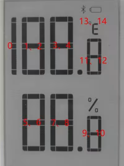
※図:1.9inch Segment e-Paper Module Manual - Waveshare Wikiより引用
のように対応していて、例えば、
26の2を出力する場合は、リストの1と2の値に何らかの値を指定します。
数字の出力に関しては、
numbers = [
    [0xbf, 0x1f],  # 0
    [0x1f, 0x00],  # 1
    [0xfd, 0x17],  # 2
    [0xf5, 0x1f],  # 3
    [0x47, 0x1f],  # 4
    [0xf7, 0x1d],  # 5
    [0xff, 0x1d],  # 6
    [0x21, 0x1f],  # 7
    [0xff, 0x1f],  # 8
    [0xf7, 0x1f]   # 9
]
の値を使用します。
2という数字を出力する場合は、[0xfd, 0x17]の値の組み合わせを用います。
26℃の℃の箇所(リストの13と14)では、
radix_point = 0x20
degree_centigrad = 0x05
Fahrenheit_degree = 0x06
BLE = 0x08
POW = 0x10
First_black = 0x1f
First_white = 0x00
の箇所のパラメータのサンプルから選んで使用します。
ここから今回利用したI2Cというシリアル通信について触れていきます。
今回、マイクロビットとe-paperをジャンパワイヤで繋ぐ時、
| e-paper | microbit |
|---|---|
| VCC | 3.3V |
| GND | GND |
| SDA | GPIO 20 |
| SCL | GPIO 19 |
| RST | GPIO 0 |
| BUSY | GPIO 1 |
になるように繋ぎました。
SDAはSerial Dataの略で、データ用の信号線になります。
一方、SCLはSerial Clockの略で、クロック用の信号線になります。
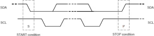
※図:1.9inch Segment e-Paper Module Manual - Waveshare Wikiより引用
I2CではSDAでデータを送信する際、SCLがあり自身でクロックを発生させることで、マイクロビットでUARTを使ってみるで見たUARTのようにデータ送信側と受信側のボーレートを合わせるといった手続きが不要になります。
実際に送信されるデータの詳細には触れませんが、データを送信する時、送信の種類にコマンドとデータがあり、
スレーブのアドレス - コマンド - データ - コマンド
のような規則でデータを送信します。
※I2Cデバイスをスレーブとし、I2Cデバイスを操作するコンピュータをマスターと呼びます。
※今回のコードではI2Cデバイスに対して書き込みのみを行いましたが、I2Cには読み込みの方のモジュールもあります。
- MakeCodeでコードを書いてみよう
- MakeCodeのConnect deviceができない時の対応
- micro:bit Python Editorでコードを書いてみよう
- MakeCodeのShow data デバイスを使ってみよう
- micro:bit Python Editorのシリアルを表示を使ってみよう
- マイクロビットの無線通信の受信機側の値の取り扱い方を調べる
- マイクロビットの無線通信で常に新しい値を取得してみる
- マイクロビットの無線通信で信号の強度を変えながら値を送信してみる
- MakeCodeで潜水艦が潜るアニメーションのコードを書いてみよう
- MicroPythonで潜水艦が潜るアニメーションのコードを書いてみよう
- MicroPythonでヨットが横に移動するアニメーションのコードを書いてみよう
- MakeCodeでボタンAを押した時だけアイコンを表示してみよう
- MicroPythonでボタンAを押した時だけアイコンを表示してみよう
- マイクロビットからのシリアル通信をラズベリーパイで受信してみる
- MakeCodeでLチカをしてみよう
- MicroPythonでLチカをしてみよう
- pokitMeterでマイクロビットから発生する電流等を測定してみよう
- MakeCodeでLEDの明るさを徐々に変えてみよう
- MicroPythonでLEDの明るさを徐々に変えてみよう
- MakeCodeで270°サーボモータを動かしてみよう
- MakeCodeのPWMで270°サーボモータを動かしてみよう
- MicroPythonで270°サーボモータを動かしてみよう
- MicroPythonで360°サーボモータを動かしてみよう
- マイクロビットとモータドライバでDCモータを動かしてみよう
- ブレットボードを使ってみよう
- CdSセルとマイクロビットのAD変換で明るさを測定してみよう
- マイクロビットとタクトスイッチでプルダウン抵抗について触れてみる
- マイクロビットとタクトスイッチでプルアップ抵抗について触れてみる
- マイクロビットでUARTを使ってみる
- マイクロビットでI2C電子ペーパモジュールを使ってみる
- マイクロビットとI2C電子ペーパモジュールでデジタル温度計を造ってみる
- マイクロビットでSPIカラー電子ペーパモジュールを使ってみる
- スクラッチにマイクロビットを繋げてコードを書いてみる
- Microbit Moreとマイクロビットを繋げてコードを書いてみる
- :GAME ZIP 64でMicrobit Moreを動かしてみる
- :GAME ZIP 64とMicrobit Moreでマリオ風の操作をできるようにする
- Microbit Moreで明るさセンサーを使ってみる
- Microbit Moreの水準器を使ってスプライトを移動してみる
- Microbit Moreでマイクを使ってみる
- Microbit Moreでボールの発射ボタンを作ってみる
- マイクロビットをブルートゥースの子機(ペリフェラル)にしてみる
- ターミナルからマイクロビットにコードをフラッシングする